Table of Contents
This is the easiest DIY IoT project based on ESP8266 that does not require any technical knowledge or background in programming. It’s as simple as installing a program or app on a Windows computer, Android, or iPhone.
Earlier I built a DIY door access control using ESP8266 and MFRC522 module to unlock my main door lock using a 13.56MHz RFID card and keychain. However, to add new users or new cards or remove an existing or lost card, I had to manually modify the code and then flash it to the ESP8266 based NodeMCU module using my laptop. This isn’t convenient and thus, I looked for a better solution that allows adding and removing RFID-based access wirelessly.
Recently, I came across an ESP-RFID project on Github that looked promising. I flash the released firmware and tested it. However, even after trying and flashing older and newer stable versions, I got no luck as ESP8266 based NodeMCU was crashing and restarting as I connected the MFRC522 or PN532 RFID reader/writer module.
But eventually, I was able to figure out the issue and changed some pins to make it work. In this guide, I will show you how you can use the ESP-RFID- An RFID-based access control using ESP8266 (NodeMCU) and RC522, PN532, Wiegand, or RDM6300 RFID sensor module.
Also Read: How to Make DIY IR Blaster using ESP8266 (NodeMCU)
Parts You’ll Need
- ESP8266 NodeMCU
- An RFID Reader/Writer module, such as RC522, PN532, Wiegand, or RDM6300
- A Buzzer
- Jumper wires
- 5V Power Supply (Use any Micro USB phone Charger)
- A Micro USB Cable
- An electronic door lock
Steps to Build a RFID-Based DIY Door Access Control Unit
Follow these steps to set up and build the DIY RFID-based door access control.
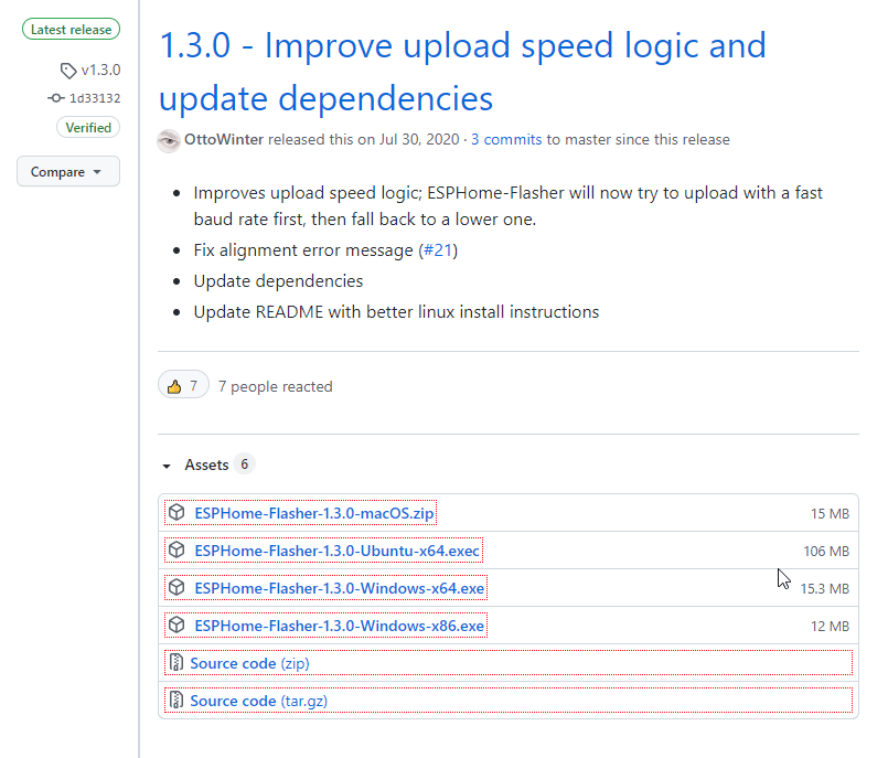
Step 1: Download ESPHome Flasher Tool
ESPHome Flasher tool is available for Windows, macOS, and Linux systems. The utility will help you flash the firmware on ESP8266 NodeMCU.
Step 2: Download the Firmware
Visit this page to download the latest stable binary or firmware file for ESP8266. I have used all but found v1.3.1 to be working perfectly fine.
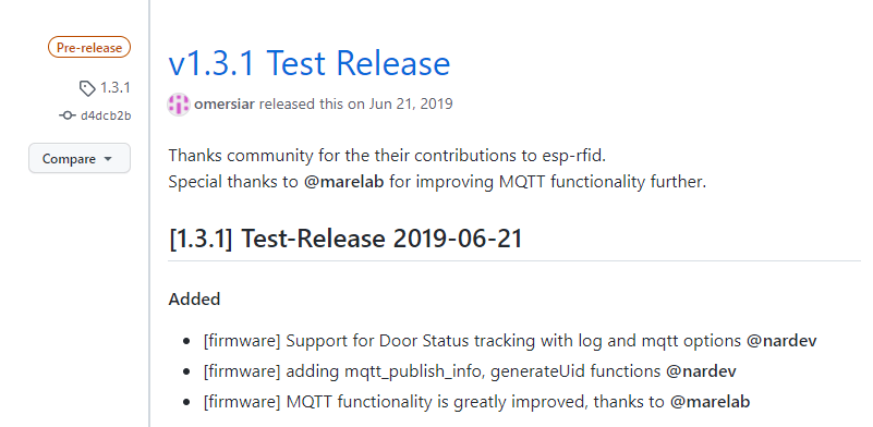
Extract the firmware file to any location. It contains multiple files including the Flash.bat file that you can use to flash the firmware. However, we are going to use the ESPHome Flasher tool.
Step 3: Flash the Firmware
Launch ESPHome-Flasher.exe and then follow these steps,
- Connect ESP8266 NodeMCU to your system using micro USB cable. Make sure you have installed CH340 drivers otherwise the NodeMCU won’t be detected.
- Select the COM port from the Serial port drop-down
- Click ‘Browse‘ and navigate to the location where you extracted the firmware files. Choose generic.bin file and then click ‘Flash ESP.’
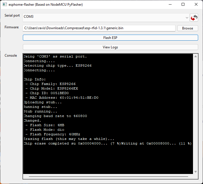
- Wait for it to finsih flashing the binary
Step 4: Setup ESP-RFID
After the firmware is flashed, the ESP8266 NodeMCU restarts in AP Mode. Follow these steps to connect and set up the ESP-RFID.
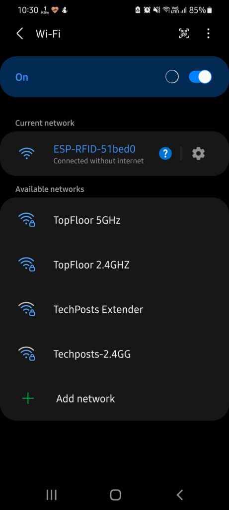
- On your Android, iPhone or PC, go to WiFi settings and connect to ESP-RFID-xxxx network. It’s an open network and thus, you don’t need a password.
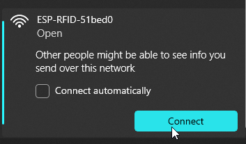
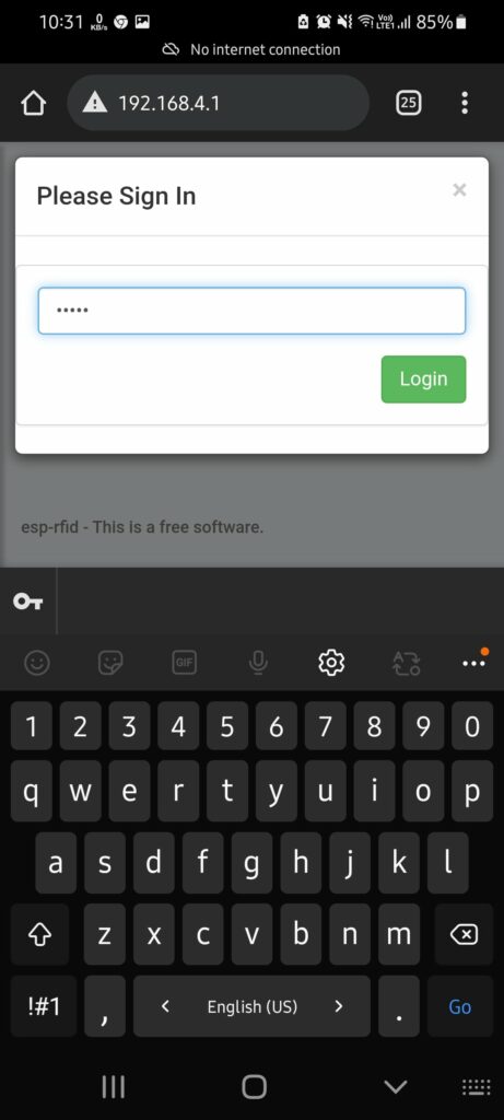
- Once connected, open web browser and type 192.168.4.1, and press ‘Enter‘ or tap ‘Go‘ on your device.
- Enter admin in the password filed and tap the ‘Login‘ button.
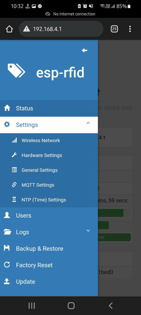
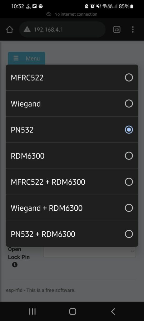
- Go to Settings>Hardware Settings and choose the RFID reader type from the drop-down. You can choose MFRC522, PN532, Wiegand, or RDM6300.
- Then choose the SPI SS pin from the drop-down. The documentaion suggests choosing GPIO-15 but it leads to crash. Thus, choose GPIO-2.
- Keep WiFi led, Door Status, Open Lock Pin blank or default.
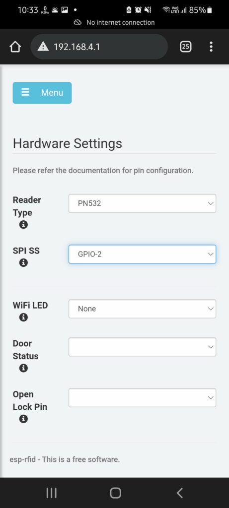
- In Relay type, select ‘Active Low‘ or ‘Active High‘ based on your relay type. You can keep the relay in high or low state by default once you select the option.
- In Relay Pin, choose GPIO-4.
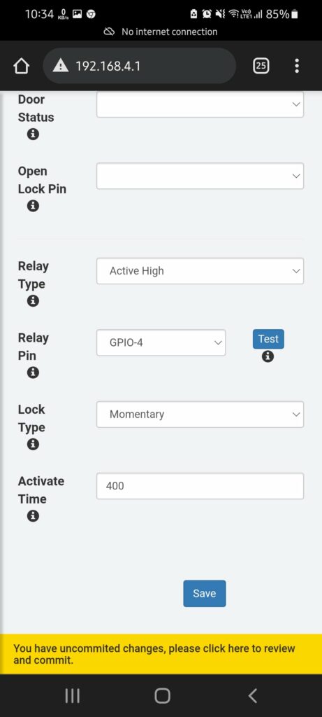
- In Lock type, select Momentary and then enter the Activate Time. I sugegst entering 200-400 for electric door lock operated by push switch. Increase the Activate Time value to 1000 or 2000 if you are using a solenoid lock.
- Click or tap on the ‘Save‘ button.
- Go to NTP (Time) Settings and tap ‘Sync Browser Time to Device.’ This will update the ESP8266 time.
- Go to Settings>Wireless Network and then change SSID and enter a password. Keep WiFi mode to ‘Access Point‘ and click ‘Save.’
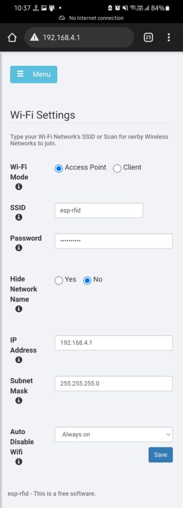
- Then goto Settings>General Settings and change the admin password. Click ‘Save.’ This will secure the device further.
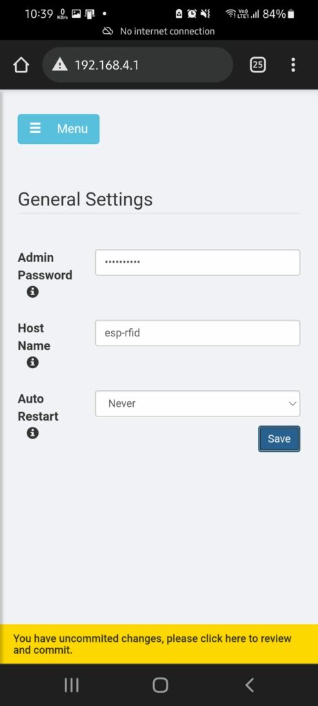
- Then tap on ‘You have uncommitted changes, …‘ text at the bottom.
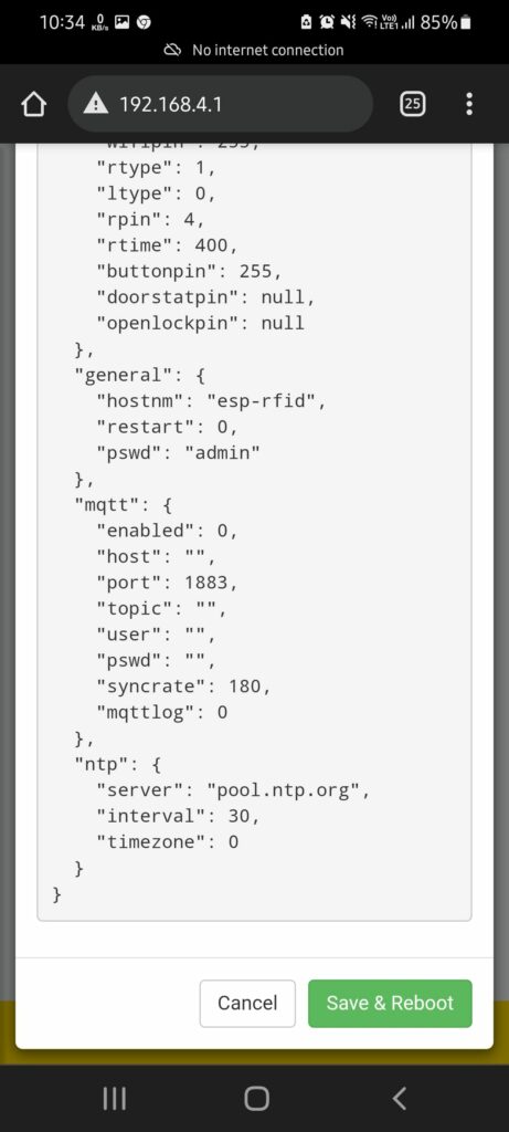
- Tap on ‘Save & Reboot‘ button.
This will save the changes and reboots the ESP8266 NodeMCU module. To connect, open WiFi settings and connect to esp-rfid using the password you changed and then login with the new password (if you have changed it).
Recommended for You: Build WiFi Repeater using ESP8266 to Extend WiFi Coverage
Step 5: Connect the RFID Reader Module to ESP8266 NodeMCU
Refer to the following pin layout table to connect the MFRC522, PN532, or other RFID modules to ESP8266 NodeMCU in SPI mode.
| ESP8266 | NodeMcu/WeMos | Wiegand | PN532 | MFRC522 | RDM6300 |
|---|---|---|---|---|---|
| GPIO-02 | D4 | SS | SDA/SS | ||
| GPIO-13 | D7 | D0 | MOSI | MOSI | |
| GPIO-12 | D6 | D1 | MISO | MISO | |
| GPIO-14 | D5 | SCK | SCK | TX | |
| GPIO-04 | D2 | ||||
| GPIO-05 | D1 |
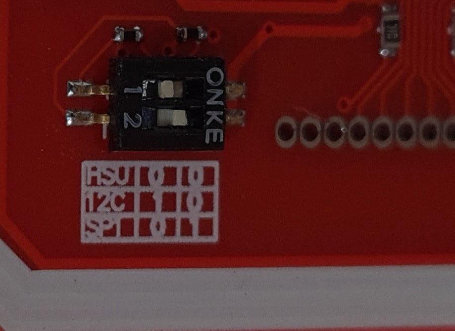
IMPORTANT NOTE: Please connect the pins correctly. Also, enable SPI mode if you are using the PN532 RFID sensor module by moving the toggle switch as shown in the image below.
Then connect the NodeMCU to the power supply and follow these steps,
- Connect your PC or phone to the esp-rfid Wireless network and visit the 192.168.4.1 address in your browser.
- Enter admin as password to log in and then go to Users
- Now show an RFID card or tag in front of the RFID reader module which you connected to NodeMCU
- The card UID details will pop up automatically. Enter the User Name or Lable the card and then select ‘Always‘, ‘Disabled‘ or ‘Admin‘ from the Access Type drop-down. Watch the following video to learn how it’s done.
- Tap ‘Save Changes‘
- Repeat the steps to add as many RFID cards. You can add up to 1000 cards.
NOTE: ‘Always‘ allows access and unlocks the door, ‘Disabled‘ denies access, and ‘Admin‘ allows access to the door.
Must Read: Home Automation with Google Assistant and Alexa under $10 using ESP8266
Now if you show a card, based on the Access Type you choose, the door will be either unlocked or remain closed. You can add, remove, or edit the card details or access them on the go. Just connect to the ESP-RFID network, access the admin pane via 192.168.4.1, and then add more cards or remove them as per your needs.
You don’t need a PC. You can further change the Admin password, add a password to the WiFi Access Point, or connect the ESP8266 to your WiFi network in Client mode. However, I suggest keeping it in AP mode.
You can also check the logs to check who accessed the door and at what time. However, in AP mode, the time may be incorrect. You can connect the ESP-RFID to your WiFi network to keep the time correct.
So that’s how you can build your DIY wireless door access control system that collects access logs and event logs. For more such interesting how-to guides and tutorials on IoT projects, subscribe to our blog and YouTube channel.
For help, you can always reach us via the comments below.

